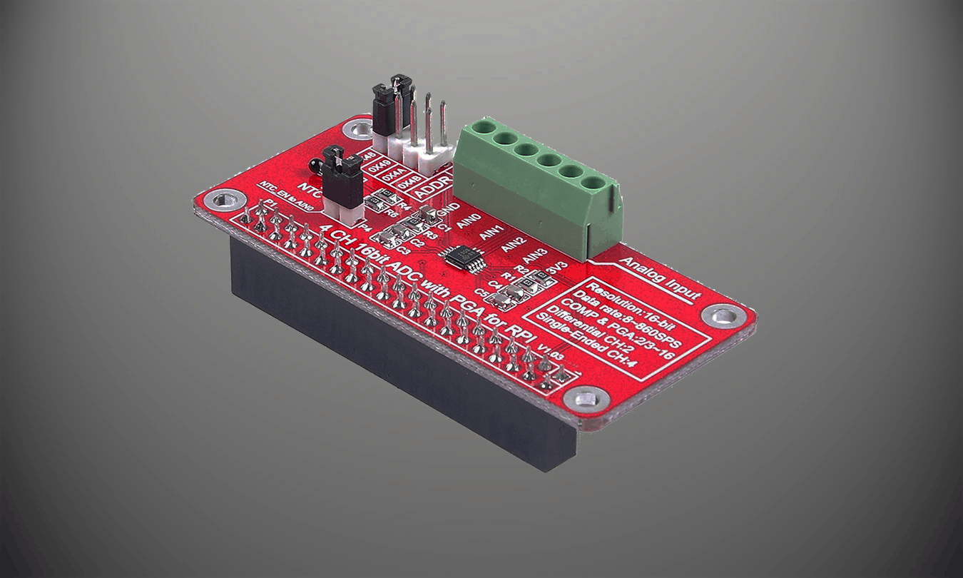
Basic tutorial of how to setup an ADS1115 based ADC with the Raspberry Pi.
ADS1115 Specifications: https://www.ti.com/lit/ds/symlink/ads1114.pdf?ts=1609357468599&ref_url=https%253A%252F%252Fwww.google.com%252F
PARTS:
CanaKit Raspberry Pi 4 4GB Starter Kit – https://amzn.to/2Jrlbfj
ADS1115 ADC – https://amzn.to/3o12cHi
Dupont Jumper Cables – https://amzn.to/3n1Cql1
Capacitive Soil Mosisture Sensor – https://amzn.to/3pC7WI6
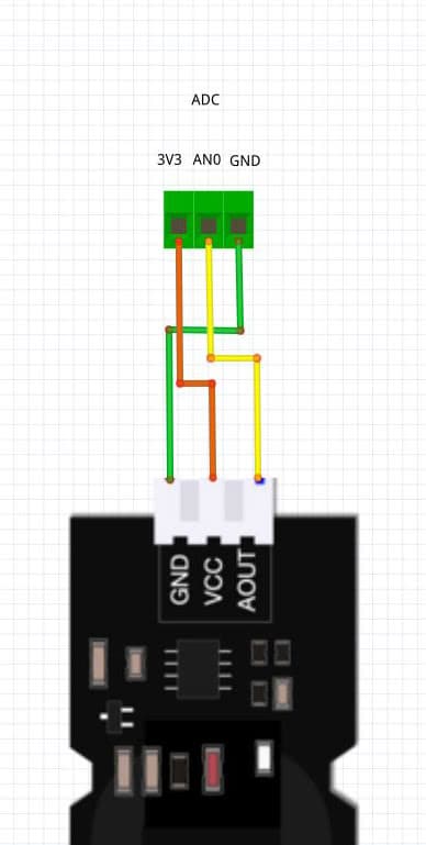
SCHEMATIC:
ADC | Sensor
3V3 <–> VCC
AN0 <–> AOUT
GND <–> GND
SETUP:
1. Enable I2C interface
sudo raspi-config
1. Select “Interfacing Options”
2. Select “I2C”
3. Select “Yes”
4. Select “Finish”
2. Check I2C device
sudo i2cdetect -y 1
You should see “48” if device is detected. (address set by default)
3. Install ADS1115 Library
sudo pip3 install adafruit-circuitpython-ads1x15
CODE:
adafruit-circuitpython-ads1x15 github: https://github.com/adafruit/Adafruit_CircuitPython_ADS1x15
import time
import board
import busio
import adafruit_ads1x15.ads1015 as ADS
from adafruit_ads1x15.analog_in import AnalogIn

# Create the I2C bus
i2c = busio.I2C(board.SCL, board.SDA)

# Create the ADC object using the I2C bus
ads = ADS.ADS1015(i2c)

# Create single-ended input on channel 0
chan = AnalogIn(ads, ADS.P0)
# chan_2 = AnalogIn(ads, ADS.P1)

# Create differential input between channel 0 and 1
# chan = AnalogIn(ads, ADS.P0, ADS.P1)

print("------{:>5}\t{:>5}".format("raw", "v"))

while True:
    print("CHAN 0: "+"{:>5}\t{:>5.3f}".format(chan.value, chan.voltage))
    # print("CHAN 1: "+"{:>5}\t{:>5.3f}".format(chan_2.value, chan_2.voltage))
    time.sleep(0.5)